SPI
Serial Peripheral Interface or SPI is a synchronous serial communication protocol that provides full – duplex communication at very high speeds. Serial Peripheral Interface (SPI) is a master – slave type protocol that provides a simple and low cost interface between a microcontroller and its peripherals.

SPI Signals
SCLK (serial clock): The device that generates the clock signal is called the main. Data transmitted between the main and the subnode is synchronized to the clock generated by the main. SPI devices support much higher clock frequencies compared to I2C interfaces. Users should consult the product data sheet for the clock frequency specification of the SPI interface.
SDI/SDO (serial data in / serial data out) or MOSI/MISO (Master Out Slave in / Slave In Master Out): MOSI and MISO are the data lines. MOSI transmits data from the main to the subnode and MISO transmits data from the subnode to the main.
CS/SS (chip select / slave select): The chip select signal from the main is used to select the subnode. This is normally an active low signal and is pulled high to disconnect the subnode from the SPI bus. When multiple subnodes are used, an individual chip select signal for each subnode is required from the main.
SPI Hardware
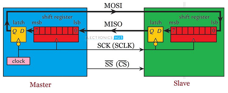
From the image, the Master device consists of a Shift Register, a data latch and a clock generator. The slave consists of similar hardware: a shift register and a data latch. Both the shift registers are connected to form a loop. Usually, the size of the register is 8 – bits but higher size registers of 16 – bits are also common.
During the positive edge of the clock signal, both the devices (master and slave) read input bit into LSB of the register. During the negative cycle of the clock signal, both the master and slave places a bit on its corresponding output from the MSB of the shift register.
Hence, for each clock cycle, a bit of data is transferred in each direction i.e. from master to slave and slave to master. So, for a byte of data to be transmitted from each device, it will take 8 clock cycles.
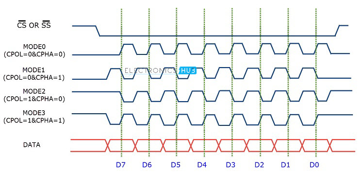
SPI Modes of Operation
- CPOL (clock polarity): controls the idle state value of the clock when no data is being transferred
- CPHA (clock phase): controls at which clock edge of the SCLK (1st or 2nd) the data should be sampled by the slave
| SPI Mode | CPOL | CPHA | Clock Phase Used to Sample and/or Shift the Data |
|---|---|---|---|
| 0 | 0 | 0 | Data sampled on rising edge and shifted out on the falling edge |
| 1 | 0 | 1 | Data sampled on the falling edge and shifted out on the rising edge |
| 2 | 1 | 0 | Data sampled on the rising edge and shifted out on the falling edge |
| 3 | 1 | 1 | Data sampled on the falling edge and shifted out on the rising edge |
Daisy Chain
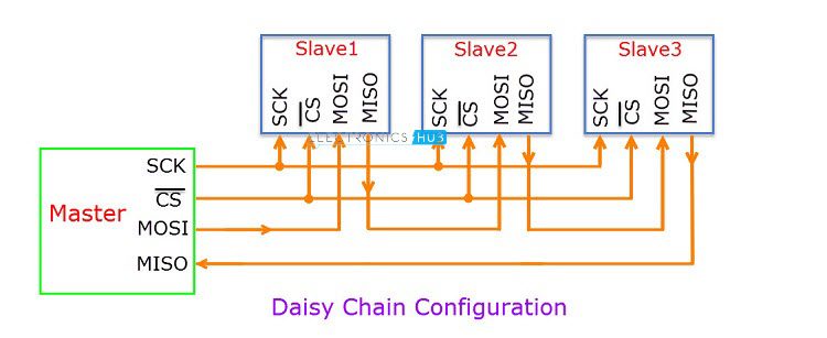
In Daisy Chain Configuration, only a single Slave Select line is connected to all the slaves. The MOSI of the master is connected to the MOSI of slave 1. MISO of slave 1 is connected to MOSI of slave 2 and so on. The MISO of the final slave is connected to the MISO of the master.
Consider the master transmits 3 bytes of data in to the SPI bus. First, the 1st byte of data is shifted to slave 1. When the 2nd byte of data reaches slave 1, the first byte is pushed in to slave 2.
Finally, when the 3rd byte of data arrives in to the first slave, the 1st byte of data is shifted to slave 3 and the second byte of data is shifted in to second slave.
If the master wants to retrieve information from the slaves, it has to send 3 bytes of junk data to the slaves so that the information in the slaves comes to the master.
Applications of SPI
- Memory: SD Card , MMC , EEPROM , Flash
- Sensors: Temperature and Pressure
- Control Devices: ADC , DAC , digital POTS and Audio Codec.
- Others: Camera Lens Mount, touchscreen, LCD, RTC, video game controller, etc.
Advantages
- SPI is very simple to implement and the hardware requirements are not that complex.
- Supports full – duplex communication at all times.
- Very high speed of data transfer.
- No need for individual addresses for slaves as CS or SS is used.
- Only one master device is supported and hence there is no chance of conflicts.
- Clock from the master is configured based on speed of the slave and hence slave doesn’t have to worry about clock.
Disadvantages
- Each additional slave requires an additional dedicated pin on master for CS or SS.
- There is no acknowledgement mechanism and hence there is no confirmation of receipt of data.
- Slowest device determines the speed of transfer.
- There are no official standards and hence often used in application specific implementations.
- There is no flow control.